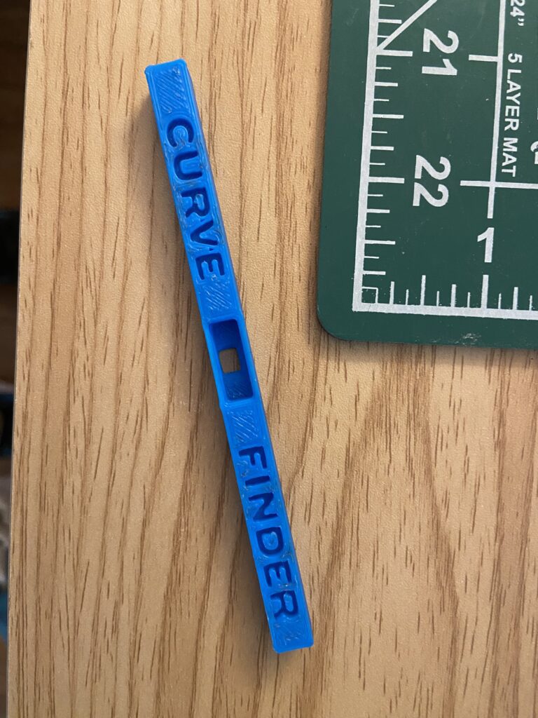
I wanted to develop a an attachment for my calipers that could improve my workflow and modeling when it came to modeling curves of mating surfaces. The goal was to quickly model arcs unknown curves. I created multiple versions; one flat and one curved, to measure concave and convex curves.
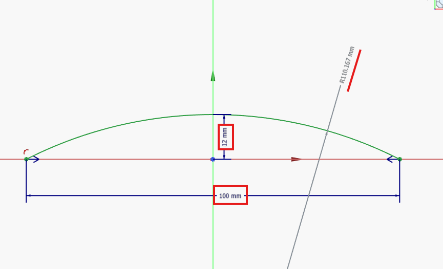
When modeling an arc in CAD, you can fully constrain in basically two operations:
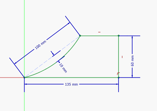
- The distance from the two end points
- The distances from the top of the curve to the datum that is common to those two points (in this case, this is the X-axis)
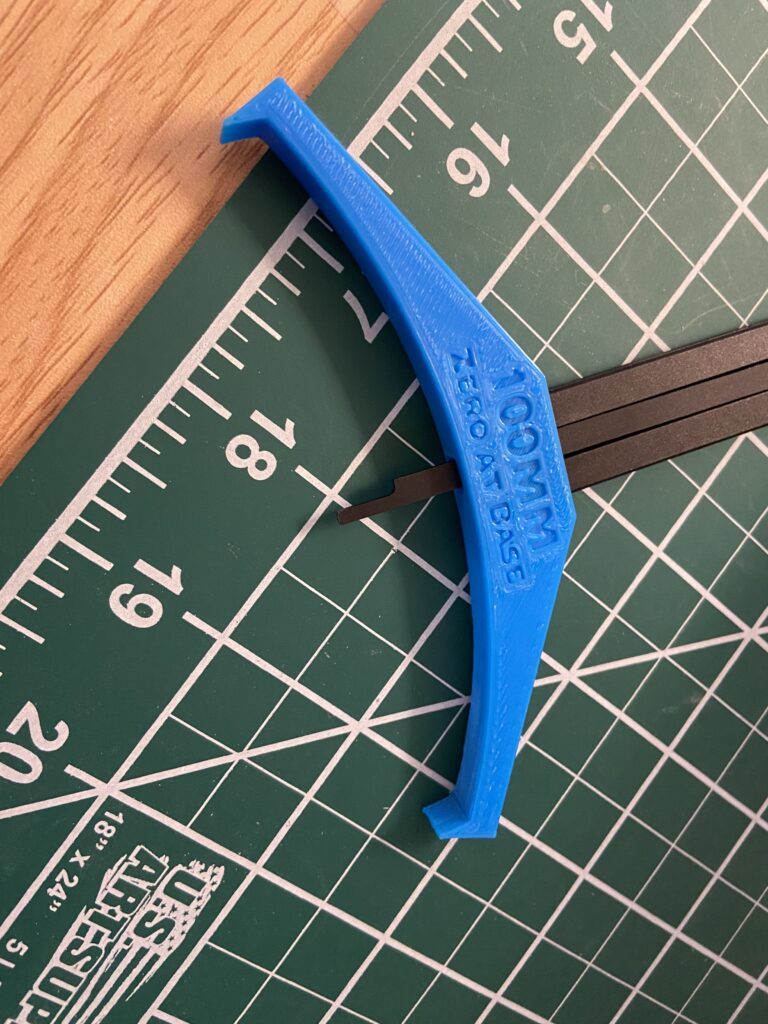
This tool helps provide those two constraint values. The first, the distance between the end arc points, will always be the two end post distances of the tool. The one in my pictures has a distance of 100mm.
The other parameter is obtained using the caliper reading. The caliper sits inside the tool cavity and utilizes the end of the caliper end post (?). You zero the caliper on a flat surface so that the end post is all the way down. If you own analog calipers, you would calculate the displacement.
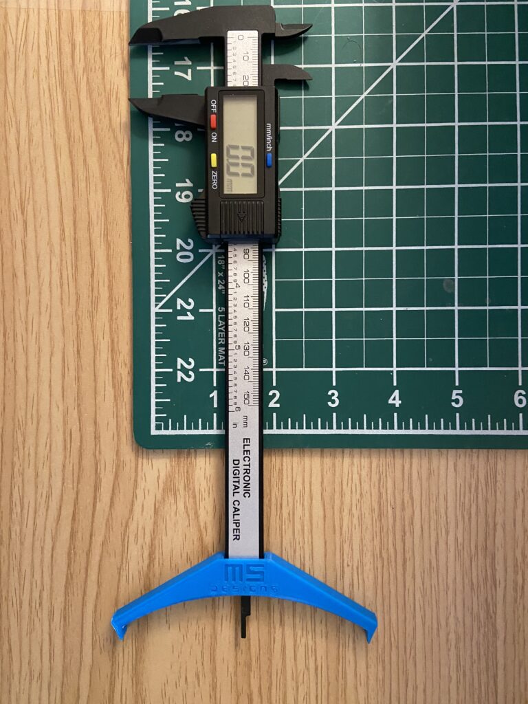
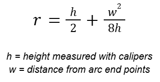
Next, you would place on your curved surface and use that reading (will be negative) to constrain the distance from the top of the curve to the plane of the two points. The radius dimensioning tool is then used to get a value based on your parameters. You can also use this formula to find the radius dimension.
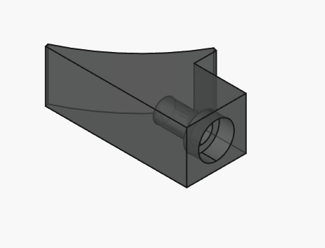
Here, I have model that uses the curve parameters on a part. Of course, I modeled is using the 100mm default value, but with your radius dimension, you can create any kind of part.
I came to find out that other smart folks created similar versions on Printables, etc… To me, this was a fun project either way.
I am exploring options to create these out of aluminum for more precise measuring, or add metal posts at the end to provide rigid points instead.