Repetition of similar tasks can often contribute to errors. This common human behavior applies to processes just as much as it does to systems within products. I have found that generating company process drawings for customer parts in a short period of time leads to many small (and large) mistakes. To create a print, so much information is processed and then translated into views and notes for production. The issues is that most of the information is new, trivial, or partly unknown at the time of a drawing. In small companies, or for busier staff personnel, you may be in the middle of several part drawings, or get interrupted throughout the day. There are countless opportunities to make an error.
So how about we redesign the process, or develop a system to help? One afternoon, I generated a checklist prototype for myself when creating drawings. Checklists are helpful, but not always for those with ADD/ADHD or other unique brains. My mind jumps around too much. So, what if we map the checklist right onto the drawing template itself, and made them short?
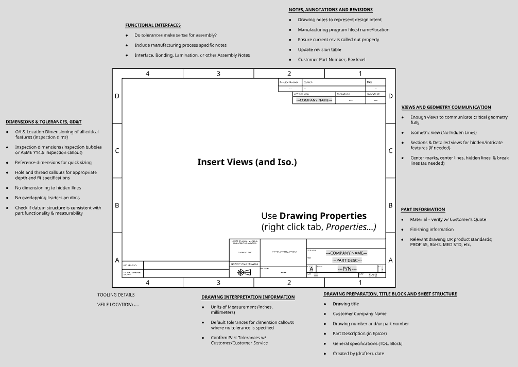
When importing the template (.dwt) into a new drawing, you are confronted with small checklists throughout the template, proximate to their relevant information fields. I also added steps to help automate many menial tasks such as adding the customer name multiple times, using variable placeholders such as the revision level based on the information typed into the properties field. You simply open the Properties menu, and type in the real values where the placeholders are.
I could make this template even better by numbering the fields/information in a way that coincides with the company Notice to Engineering. Or perhaps color coding the text in a way that groups similar information together. That way when going through it, nothing is left off from the customer or customer service.
My brain enjoys crossing off the mini checklist items as I populate the drawing. If I remove the checklist item, then it is because I have it typed in or presented on the drawing.
The best part is, a non-engineer can work with and use this drawing template (apart from proper dimensioning, tolerancing, and using CAD, of course). It mostly standardizes how we create engineering prints. By implementing this system, we are ensuring all drawings look the same, present the same information, and do not allow for much room for assumptions by production.
In Summary, the benefits are:
- Uniformity of prints; information is always present, clear, and
- Accuracy of prints (Significant cost savings in eliminating scrap or costly production mistakes)
- Cost value of the time savings by eliminating the number of draft revisions
- You are working WITH peoples’ humanity, not against it
Below are the checklist items referenced above:
Insert Views (and Iso.)
Use Drawing Properties (right click tab, Properties…)
DRAWING PREPARATION, TITLE BLOCK AND SHEET STRUCTURE
- Drawing title
- Customer Company Name
- Drawing number and/or part number
- Part Description (in ERP system)
- General specifications (TOL. Block)
- Created by (drafter), date
- Customer Part Number, Rev level
DRAWING INTERPRETATION INFORMATION
- Units of Measurement (inches, millimeters)
- Default tolerances for dimension callouts where no tolerance is specified
- Confirm Part Tolerances w/ Customer/Customer Service
PART INFORMATION
- Material – verify w/ Customer’s Quote
- Finishing information
- Relevant drawing standards; Prop 65, RoHS, Other product std, etc.
NOTES, ANNOTATIONS AND REVISIONS
- Drawing notes to represent design intent
- Manufacturing program file(s) name/location
- Ensure current rev is called out properly
- Update revision table
DIMENSIONS & TOLERANCES, GD&T
- OA & Location Dimensioning of all critical features (inspection dims)
- Inspection dimensions (inspection bubbles or ASME Y14.5 inspection callout)
- Reference dimensions for quick sizing
- Hole and thread callouts for appropriate depth and fit specifications
- No dimensioning to hidden lines
- No overlapping leaders on dims
- Check if datum structure is consistent with part functionality & measurability
FUNCTIONAL INTERFACES
- Do tolerances make sense for assembly?
- Include manufacturing process specific notes
- Interface, Bonding, Lamination, or other Assembly Notes
VIEWS AND GEOMETRY COMMUNICATION
- Enough views to communicate critical geometry fully
- Isometric view (No hidden Lines)
- Sections & Detailed views for hidden/intricate features (if needed)
- Center marks, center lines, hidden lines, & break lines (as needed)